
A Checklist of Pre-Installation Preparations for PSA Nitrogen Generation Systems
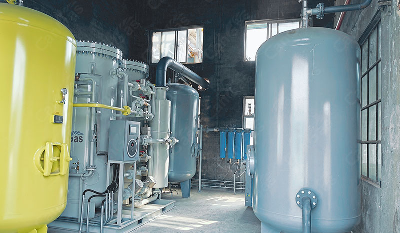
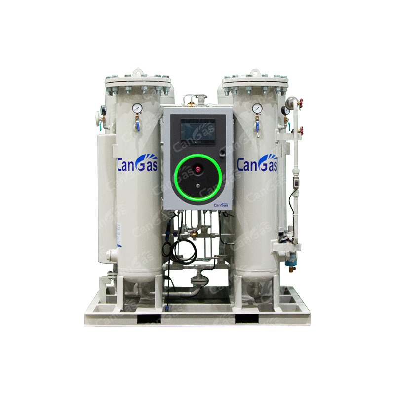
Once a PSA nitrogen generator has completed commissioning, the subsequent on-site installation of the equipment must not be overlooked; indeed, it requires equally professional, meticulous, and comprehensive guidance. This is a critical step in ensuring the system's continuous and stable operation, as well as guaranteeing streamlined workflows, convenient maintenance, and full compliance with safety regulations.
I. Site Planning and Layout Design
1. Space Assessment
· Measure the length, width, and height of the installation site, and verify the dimensions of the equipment components (i.e., each unit within the PSA nitrogen generation system).
· When planning the equipment placement, ensure a clearance of approximately 1.5 meters is maintained to facilitate future operations and maintenance access.
2. Equipment Layout Principles
· Minimize Piping: Reduce the number of bends and the overall length of compressed air and nitrogen pipelines to minimize pressure drop losses.
· Modular Arrangement: Adopt a linear ("I-shaped") or L-shaped layout to ensure a compact footprint and facilitate future system expansion.
· Heat Source Isolation: Route the heat dissipated by the equipment outdoors or away from electrical control cabinets to prevent high temperatures from compromising the service life of electrical components.
II. Foundation Construction and Installation Essentials
1. Floor Load-Bearing Capacity and Levelness
· The equipment foundation must meet the required load-bearing specifications (the total weight of the complete system can amount to several tons).
· The floor surface where the equipment is placed must be level, wear-resistant, and slip-resistant.
2. Installation of the Compressed Air Pre-treatment System
· Connect the components in the following sequence: Air Compressor Outlet → Air Storage Tank → Refrigerated Air Dryer → Three-Stage Filtration System → PSA Nitrogen Generator Main Unit.
· The distance between the pre-treatment equipment and the main generator unit should not be excessive, as this can lead to pressure loss (approximately 0.1 bar of pressure drop occurs for every additional 10 meters of piping).
3. Piping and Valve Design
· Main pipelines should be constructed using stainless steel or galvanized steel piping.
· Install shut-off valves and pressure gauges at critical junctions (e.g., the storage tank outlet and equipment inlet) to facilitate sectional maintenance and troubleshooting.
· Install a sampling port on the nitrogen outlet pipeline to allow for purity testing.
4. Electrical System Installation
· Provide a dedicated power supply for the equipment, utilizing a separate distribution cabinet distinct from the power circuits used for lighting and ventilation.
· Ensure the control cabinet is positioned no more than 3 meters away from the main generator unit; all wiring should be routed through protective conduits to prevent electrical interference.
III. Safety and Environmental Control
1. Ventilation and Heat Dissipation
· The equipment room must be equipped with ventilation ducts to prevent high indoor temperatures from degrading the performance of the molecular sieves.
· A clearance of at least 1 meter must be maintained on the heat-dissipation side of the main unit to facilitate heat dissipation.
2. Environmental Temperature and Humidity Control
· Operating Temperature: 5–40°C.
· Operating Humidity: ≤80% RH.
· The equipment room must be situated away from areas with severe air pollution.
IV. Provisions for Future Expansion
If future expansion of gas supply capacity is anticipated, the following provisions should be made:
· Pipe interfaces should be fitted with flanges or quick-connect couplings to facilitate future capacity expansion.
· Depending on the specific situation, a 20% buffer zone should be allocated around the site to accommodate the addition of new modules (e.g., a secondary boosting system).